Background
I’ve had a project on the back burner for a long time to make a replacement PCjr power supply board. The original power supply for the unit is split into two parts. There is an external power brick that contains an AC transformer that steps AC mains down to about ~18 VAC. It plugs into an internal PCB that rectifies the AC and then linearly regulates that voltage down to +12V, +5V, and -12V DC. There are ‘long’ boards and ‘short’ boards. However both designs include power ICs, large tank capacitors, and active linear regulators that operate in the transient region consuming most of the difference between 18 VAC to 5 VDC in the form of heat.
The other problem with IBM’s original design is the external transformer – it is never switched off mains. Instead, the wall connected side of it continually resonates on line voltage – even when switched off. So PCjr systems that have sat powered off for decades still accumulated wear entropy in the transformer. Thus it became a high failure component in the design. Many fewer transformers survived till now than system units. Out of 8-9 PC systems I own, I only had 2 working power bricks. I needed a solution.
Overview
Recently a YouTuber and PCjr community member AkBKukU made a ATX to PCjr power slot adapter for a PicoPSU. He also 3D printed a cleaver bracket to route ATX power-on to a switch on the back of the unit. It creates a completely self-contained solution with the exception of the PicoPSU’s external AC to +12V power converter brick.
His design works and make a convenient replacement solution. But I figured I would dust off my old project and take a slightly different approach. What I came up with is in some ways better and in a few ways worse. I’ll explain.
My design
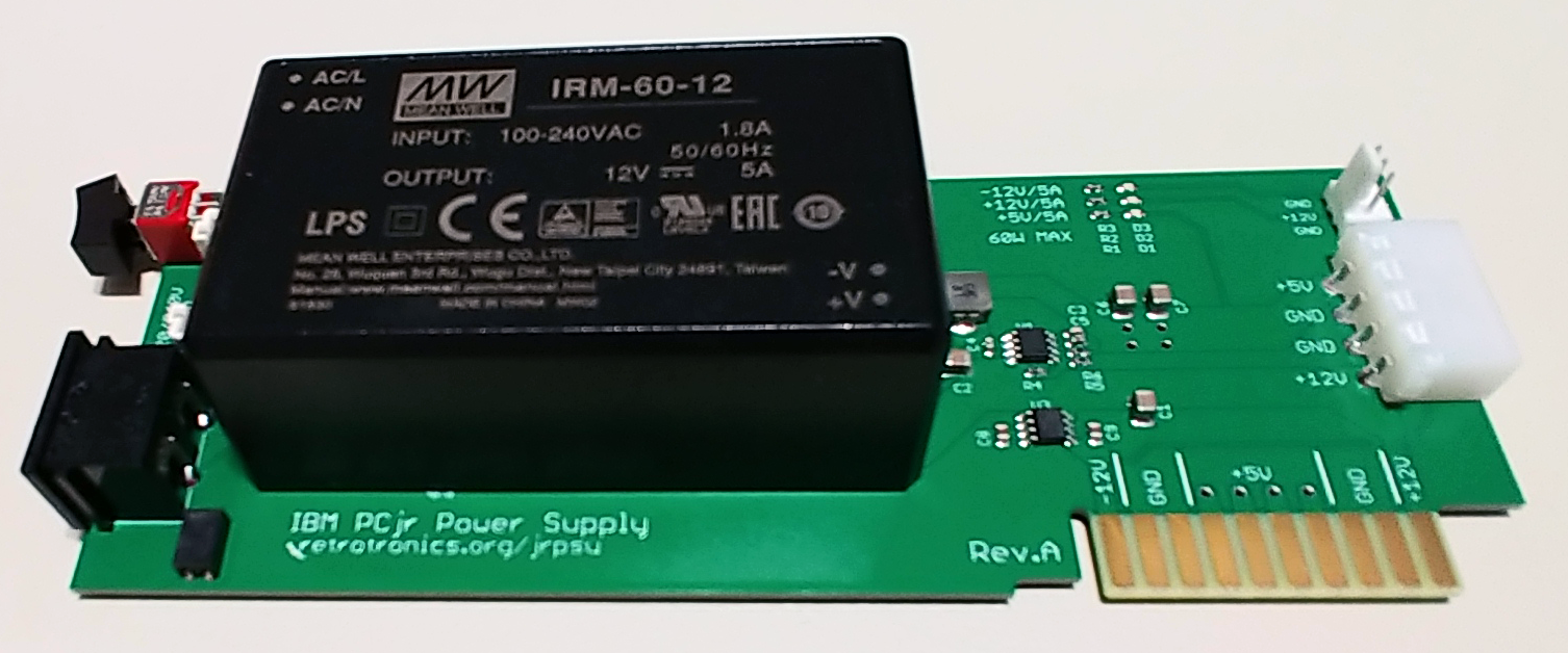
My main motivation was to eliminate the external power brick all together. One of the biggest developments to this end since the last time I put down the project was the introduction of the IRM-60 series power supplies from MeanWell. These are sealed, self-contained, PCB mount AC to DC switch mode converters rated at 60W. They are also small enough to fit within dimensions of the PCjr power supply board. 60W is also nearly twice the original 33W power supply rating. So it will eliminate the need for a power supply side car in most system configurations.
A quick addition of an IEC320-C8 power entry connector, a 5 x 20 mm fuse holder, and a DPDT AC rated power switch ensures a universal power conversion from any world standard outlet – 120V/60Hz or 240V/50Hz – to a stable 5A rated 12V main power output rail. To make 5V, I chose a Diodes, Inc AP65550SP switching regulator that is rated at 5A output. It switches at 650 KHz and in this configuration requires a rather modest 3.3uH inductor. Lastly to make -12V, I chose a Maxim ICL7662 inverting charge pump regulator. It makes -Vout = Vin, is self contained in a single SOIC-8, and requires no additional external components besides capacitors.
Each component in the system is rated for 5A on the individual rails but the system is limited to 60W overall minus the switching overhead of each converter. This is far greater than the original system specs below:
| Rail | Original PCjr | New Board |
| +12V | 1.2A | 5A |
| +5V | 3.6A | 5A |
| -12V / -6V | .025A | 5A |
The original power supply only provided .4 A @ 5V on the side-car connector and no available margin for +/- 12V. This version supplies a total of 1.9A 5V headroom for the side-car connector (9.5 W) and additionally allows the expansion cards to draw from +/- 12V.
-6V vs -12V
The original PCjr technical reference specs -6V as the third output power rail (in addition to +5V and +12V). However both the ATX2PCjr design above and all the original IBM power supply boards I have output -12V on that rail. The only things that use -6/-12V are the EIA-232 line driver for the serial port, a LM358 R2R op-amp on the cassette input, and a LM358 R2R op-amp on the sound output. All three devices accept an input range of at least -15V. It is unclear at this time what output level issues this will cause. I haven’t yet validated those sections of the system board. But if the original IBM design is safe at -12V, any replacement should behave similarly. There are a few typos in the power supply section of the technical reference. It may have been an uncorrected documentation issue.
The PCBs themselves are manufactured at PCBcart.com and include hard gold fingers and LED status for all three rails.
Efficiency
My system unit had the original ‘long’ IBM supply board and power brick. It is a stock unit aside from a JR-IDE board and NetPi-IDE emulator plugged into the side. Sitting idle at a DOS prompt, the system unit pulls ~34W at the outlet measured with an external power meter. With the new PSU board in the same configuration, the system unit pulls ~23W under the same idle conditions. These numbers do not include the monitor.
Powered off, the previous original power supply pulled ~4W. The new supply hard switches AC mains. So in the off position, it pulls a true 0 W.
A/C Mains Voltage Warning
ATTENTION! Due to the fact this power supply design is completely self-contained, there is AC mains voltage present on the card. It is exposed on both the component side and the non-component side of the PCB in the rear section of the board. On the component side, the switch leads and the exposed parts of the fuse carry AC voltage. On the non-component side all the pin-tails for the power entry connector, fuse holder, power switch, and MeanWell power supply module carry AC mains voltage.
I am not used to a power supply card carrying AC voltage. I have already reached in and tried to remove the card a few times out of habit with the power cord connected and the unit powered off. I’ve already been bit a few times. Please ensure the power cord is removed from the supply board before removing the top cover – especially if you live in a 240V country!
I am in the process of designing a 3D printed cover for the rear section of the board to shield human contact from the AC touch points. Until I do this, I will likely not sell these board unless I know the buyers and they are briefed on the dangers.
Schematic
pcjr_psu_reva
Repository and Downloadable Files
This power supply design is a fully open-source hardware project. A subversion repository is hosted by this site containing the latest EagleCAD design files for schematic and PCB. See the links at the top of this page for the repository URL.
If I decide to sell these boards, all boards will come pre-assembled. I have a pick and place machine and will be ordering parts on Digi-Reels for direct screen printing and automated placement.
The current bill of materials is below:
| Type | Manufacturer | Part Number | Digikey | DS | Description | Per Board | Price | IDs |
| PSU | Mean Well | IRM-60-12 | 1866-3063-ND | DS | AC/DC Converter Module 12V 60W | 1 | $16.58 | U2 |
| Conn | Molex | 0022272031 | WM4112-ND | DS | Header 3 pos .1″ Verticle Pin-guide White | 1 | $0.37 | J2 |
| Conn | TE | 641737-1 | A25430-ND | DS | 4 pos RA PTH Drive Power | 1 | $1.80 | JP1 |
| Conn | TE | 535676-1 | A26405-ND | DS | 2 pos .1″ Through Pin Header | 1 | $0.46 | |
| Conn | Qualtek | 770W-X2/10 | Q273-ND | DS | IEC320-C8 Power Entry Conn RA Pin Lug | 1 | $0.76 | J1 |
| Fuse | LittleFuse | 0235002.HXP | F2680-ND | DS | Fuse glass 2A 5x20mm | 2 | $0.45 | F1 |
| Conn | LittleFuse | 64900001039 | WK0011-ND | DS | 5x20mm 250V 6.3A Fuse Block | 1 | $0.82 | F1 |
| Switch | TE | RMD1R102M6QES | 450-2073-ND | DS | Rocker Switch DPDT 3A 120V | 1 | $4.61 | SW1 |
| IC | Maxim | ICL7662CBA+ | ICL7662CBA+-ND | DS | Charge Pump Inverting Regulator -Vin | 1 | $2.72 | U3 |
| IC | Diodes Inc | AP65550SP-13 | AP65550SP-13DICT-ND | DS | Buck 5A Adjustible Switching Regulator | 1 | $1.44 | U1 |
| L | Abracon | ASPI-0630LR-3R3M-T15 | ASPI-0630LR-3R3M-T15CT-ND | DS | 3.3uH Inductor 6.5A 28m DCR Shielded | 1 | $0.89 | L1 |
| C | Samsung | CL32A476KOJNNNE | 1276-3376-1-ND | DS | 47uF 16V 10% X5R 1210 Cap | 4 | $1.32 | C1,C2,C6,C7 |
| C | Murata | GRM219R61E106KA12D | 490-7207-2-ND | DS | SMD/SMT Layered Ceramic Capacitor 25V 10uF X5R | 2 | $0.25 | C8,C9 |
| C | Murata | GRM155R61E104KA87D | 490-5920-2-ND | DS | SMD/SMT Layered Ceramic Capacitor 25V .1uF X5R | 1 | $0.10 | C4 |
| C | Samsung | CL10B822KB8NNNC | 1276-2119-2-ND | DS | SMD/SMT Layered Ceramic Capacitor 50V 8.2nF X7R | 1 | $0.10 | C3 |
| C | Murata | GRM188R61E105KA12D | 490-3897-2-ND | DS | SMD/SMT Layered Ceramic Capacitor 25V 1uF X5R | 1 | $0.10 | C5 |
| R | Panasonic | ERJ-3EKF1001V | P1.00KHTR-ND | DS | SMT 0603 Thick Film Resistor 1% 1/10W 1K ohm | 2 | $0.10 | R1,R2 |
| R | Panasonic | ERJ-3EKF1003V | P100KHTR-ND | DS | SMT 0603 Thick Film Resistor 1% 1/10W 100K ohm | 1 | $0.10 | R4 |
| R | Panasonic | ERJ-3EKF3300V | P330HTR-ND | DS | SMT 0603 Thick Film Resistor 1% 1/10W 330 ohm | 1 | $0.10 | R3 |
| R | Panasonic | ERJ-3EKF2212V | P22.1KHTR-ND | DS | SMT 0603 Thick Film Resistor 1% 1/10W 22.1K ohm | 1 | $0.10 | R6 |
| R | Panasonic | ERJ-3EKF1243V | P124KHTR-ND | DS | SMT 0603 Thick Film Resistor 1% 1/10W 124K ohm | 1 | $0.10 | R5 |
| LED | Lite-On | LTST-C193KGKT-5A | 160-1828-2-ND | DS | LED 0603 Green 2V Clear | 3 | $0.42 | D1,D2,D3 |
| Cord | Phihong | AC15WNA | 993-1035-ND | DS | IEC320-C7 / 18 AWG / NEMA 1-15P / North America | 1 | $1.79 | |
| Cord | Phihong | AC15WEU | 993-1034-ND | DS | IEC320-C7 / 18 AWG / CEE 7/16 / Europe | 0 | $2.23 | |
| Cord | Phihong | AC15WUK | 993-1036-ND | DS | IEC320-C7 / 18 AWG / BS1363A / U.K. | 0 | $5.31 | |
| PCB | pcbcart.com | 1st Run + stencil + S&H / 50 | 1 | $8.30 | ||||
| ESD | SCS | 100510 | SCP424-ND | DS | Small ESD bag – 10×5″ | 1 | $0.12 | |
| Shipping | USPS | USPS Small Flat Rate Box | 1 | $7.20 |
Errata
Rev.A has a known issue with the silkscreen. The positions of R5 and R6 were mistakenly reversed. If placed according to silkscreen, the 5V rail will hover at ~.9V and may become unstable. Reversing the placement of the resistors will correct the problem. This will be corrected in Rev.B.
I should have placed EMI beads on each rail to prevent conducted emissions across rails and to the AC wall supply. This will be corrected in Rev.B.